TCM Memories: Zero Wait-State Speed and Determinism
https://www.renesas.com/sites/default/files/media/images/mcu-with-internal-and-external-flash.png
1. Introduction
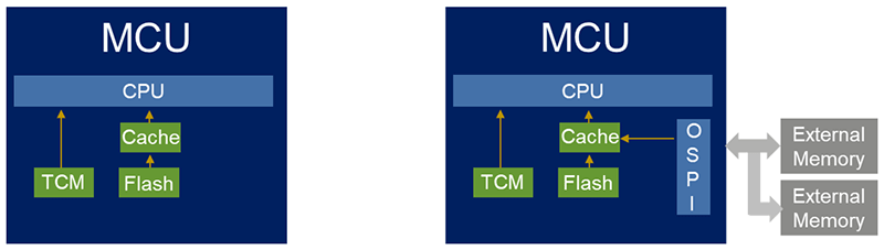
The CPU is the fastest and most impatient component in a system. Its nightmare? Waiting for memory. Accessing memory is a painful journey for the CPU—riddled with latency, bus contention, and arbitration delays caused by other masters sharing the interconnect. Left to its own desires, the CPU would prefer everything to happen at its own internal clock speed without interruptions.
To close this performance gap, designers have long sought ways to shortcut the memory access path. Caches are one such solution—but they introduce unpredictability. For real-time systems that demand deterministic behavior, this isn't acceptable. That's where Tightly Coupled Memory (TCM) comes in.
2. What Is a TCM?
Tightly Coupled Memory (TCM) is a block of SRAM directly attached to the CPU. Unlike regular memory, which sits on a shared system bus alongside peripherals and other memory regions, TCM has dedicated buses that connect it straight to the processor core. This direct connection eliminates contention and arbitration delays, making TCM what is often called a zero wait state memory.
There are typically two types of TCMs:
- ITCM (Instruction TCM) – used for instruction fetches
- DTCM (Data TCM) – used for data access
Because TCMs bypass the main system interconnect and do not compete with other bus masters, the CPU can access them immediately, without being stalled.
But TCM isn't just about raw speed—it offers something even more critical for real-time systems: determinism. Access times are fixed and predictable, which is essential for systems that require consistent timing behavior.
https://ars.els-cdn.com/content/image/3-s2.0-B9780323854948000073-f06-01-9780323854948.jpg
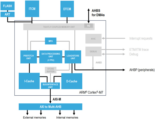
Behind the scenes, TCM is just SRAM, but it's mapped to a special region in the processor's address space. Accessing that region automatically triggers a direct path to the TCM hardware.
3. How to Use TCM Memory
Using TCMs in your embedded application begins with understanding how your microcontroller maps these memory regions. In most MCUs that support TCM—such as ARM Cortex-M7—ITCM and DTCM are mapped to fixed address regions, separate from regular RAM or flash. To take advantage of TCM, you need to manually place critical code and data into these regions, usually by modifying your linker script.
On STM32H7 devices, the ITCM is typically mapped at 0x00000000 and DTCM at 0x20000000. In your linker script, you might define a memory region like:
ITCMRAM (xrw) : ORIGIN = 0x00000000, LENGTH = 64K
DTCMRAM (xrw) : ORIGIN = 0x20000000, LENGTH = 128K
And in your C code:
__attribute__((section(".itcm"))) void fast_function(void)
{
    /* code here */
}

__attribute__((section(".dtcm"))) uint8_t buffer[256];
4. Flash vs ITCM: A Simple Benchmark Test
To demonstrate how much faster ITCM is compared to flash, we created a simple test that runs the same sequence of instructions from two different locations: once from flash, and once from ITCM.
To run a function from ITCM, we need to ensure the build system knows where to place it and that it gets copied to ITCM at startup. This involves changes in both the linker script and the startup code.
- Create a new section called
.itcmtextin the linker script and map it to the ITCM memory region (address 0x00000000 on STM32H7).
/* Memories definition */
MEMORY
{
  RAM_D1 (xrw)   : ORIGIN = 0x24000000, LENGTH =  512K
  FLASH  (rx)    : ORIGIN = 0x08000000, LENGTH = 1024K    /* Memory is divided. Actual start is 0x08000000 and actual length is 2048K */
  DTCMRAM (xrw)  : ORIGIN = 0x20000000, LENGTH = 128K
  RAM_D2 (xrw)   : ORIGIN = 0x30000000, LENGTH = 288K
  RAM_D3 (xrw)   : ORIGIN = 0x38000000, LENGTH = 64K
  ITCMRAM (xrw)  : ORIGIN = 0x00000000, LENGTH = 64K
}
    /* -------- ITCM: functions that run from Instruction TCM -------- */
    .itcmtext :
    {
      . = ALIGN(4);
      _sitcmtext = .;                 /* destination (exec addr in ITCM) */
      *(.itcmtext)                    /* functions you tag with section(".itcmtext") */
      *(.itcmtext.*)
      . = ALIGN(4);
      _eitcmtext = .;                 /* end in ITCM */
    } >ITCMRAM AT>FLASH               /* store in Flash, execute from ITCM */

_sitcmtext_load = LOADADDR(.itcmtext); - At reset, before
main()runs, copy the.itcmtextsection from flash to ITCM.
LoopFillZerobss:
  cmp r2, r4
  bcc FillZerobss
/* Copy the .itcmtext section from Flash to ITCM */
  ldr r0, =_sitcmtext        /* r0 = dest (ITCM) */
  ldr r1, =_eitcmtext        /* r1 = end  (ITCM) */
  ldr r2, =_sitcmtext_load   /* r2 = src  (Flash) */
  cmp r0, r1
  bcc CopyITCM
  b   ITCMdone

CopyITCM:
  ldr r3, [r2], #4
  str r3, [r0], #4
  cmp r0, r1
  bcc CopyITCM

ITCMdone:

/* Call static constructors */
    bl __libc_init_array
/* Call the application's entry point.*/
  bl  main
  bx  lr
The idea of the benchmark:
• We write two functions that do nothing but execute a fixed number of NOP (no operation) instructions inside a loop.
• The flash version is stored in normal program flash memory (0x08000000).
• The ITCM version is placed in the ITCM memory region (0x00000000) so the CPU fetches it directly with zero wait states.
• We use the CPU’s DWT cycle counter to measure how many clock cycles each version takes to run.
Because both functions contain the exact same instructions, any difference in execution time is purely due to the instruction fetch speed of flash vs ITCM.
the benchmark code is:
void loop_flash(uint32_t n)
{
while (n--)
{
__asm volatile(
"nop\n""nop\n""nop\n""nop\n""nop\n""nop\n""nop\n""nop\n"
"nop\n""nop\n""nop\n""nop\n""nop\n""nop\n""nop\n""nop\n"
"nop\n""nop\n""nop\n""nop\n""nop\n""nop\n""nop\n""nop\n"
"nop\n""nop\n""nop\n""nop\n""nop\n""nop\n""nop\n""nop\n"
"nop\n""nop\n""nop\n""nop\n""nop\n""nop\n""nop\n""nop\n"
);
}
}
/* ITCM function */
__attribute__((noinline, section(".itcmtext")))
void loop_itcm(uint32_t n)
{
while (n--)
{
__asm volatile(
"nop\n""nop\n""nop\n""nop\n""nop\n""nop\n""nop\n""nop\n"
"nop\n""nop\n""nop\n""nop\n""nop\n""nop\n""nop\n""nop\n"
"nop\n""nop\n""nop\n""nop\n""nop\n""nop\n""nop\n""nop\n"
"nop\n""nop\n""nop\n""nop\n""nop\n""nop\n""nop\n""nop\n"
"nop\n""nop\n""nop\n""nop\n""nop\n""nop\n""nop\n""nop\n"
);
}
}
int main(void)
{
/* I-Cache---------------------------------------------------------*/
#undef ENABLE_ICACHE
#ifdef ENABLE_ICACHE
SCB_EnableICache();
#endif /*ENABLE_ICACHE*/
/* MCU Configuration--------------------------------------------------------*/
HAL_Init();
SystemClock_Config();
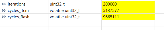
uint32_t iterations = 200000;
volatile uint32_t cycles_itcm = 0U ;
volatile uint32_t cycles_flash =0U;
/* Enable DWT cycle counter */
CoreDebug->DEMCR |= CoreDebug_DEMCR_TRCENA_Msk;
DWT->CYCCNT = 0;
DWT->CTRL |= DWT_CTRL_CYCCNTENA_Msk;
/* --- Measure Flash --- */
DWT->CYCCNT = 0;
loop_flash( iterations );
cycles_flash = DWT->CYCCNT;
/* --- Measure ITCM --- */
DWT->CYCCNT = 0;
loop_itcm( iterations );
cycles_itcm = DWT->CYCCNT ;
while (1)
{
/*infinit loop*/
}
}The ITCM run completes much faster :
5. Examples of Using TCM Memories
TCM memories are particularly useful for:
- Interrupt Service Routines (ISRs): Place time-critical ISRs in ITCM for immediate execution.
- High-Speed Data Buffers: Use DTCM for DMA buffers in high-speed ADC/DAC applications to avoid bus contention.
- Signal Processing: Implement FFTs or FIR filters with code in ITCM and working data in DTCM for maximum throughput.
- Real-Time Control Loops: Ensure consistent execution timing for control algorithms.
6. Conclusion
TCM memories provide the CPU with a direct, predictable path to critical code and data. By combining zero wait-state speed with guaranteed timing, they offer a reliable solution for meeting the strict performance requirements of real-time embedded systems. Whether you're working on motor control, digital signal processing, or any other time-sensitive application, TCM can be the key to achieving both speed and determinism in your designs.